WOOD CHIPPER
February 2021- March 2021
Team members: Sangmin Sung, Lance Haidet, Dean Smith, Rachel Greenberg
With the rising desire to chip trees in California to reduce the area of possible burns and turn the discarded wood into smaller, reusable pieces, a design team was tasked with producing a new woodchipper drivetrain and cutting design. The project hoped to make a smaller, self-contained chipper that could handle smaller pine and oak branches up to 4” in diameter. It was also assumed that the frame and casing for both towing the chipper and directing the chips after cutting were being handled by another team. As such, the major components that would need major design consideration from the design team were the chipper shaft, flywheel, bearings, motor selection, and power transmission components.

DESIGN ANALYSIS
In order to design the aforementioned components, the first step for the chipper was to do static and dynamic analysis to generate a rough design layout of the system for the following design selections: motor, clutch, shaft, pulley and belt.
The results of the static and Dynamic analysis are shown in the table below.
Files below are hand calculation works and MATLAB Simulation for the Static and Dynamic Analysis.

Motor / Clutch Selection
The motor selected was a Vanguard small block V twin engine 3057 with the gross power of 16 hp and rated rpm of 3600. The time it would take to rev up to the maximum rpm was calculated to be 5,06 seconds. A clutch with 1400 rpm engagement and service factor of 1.5 was selected as a safety measure in case an overload or jam occurred that could produce an unexpected high torque while chipping.

Shaft Selection
The design process for the shaft involved a combination of strength, fatigue and critical speed analysis. It was assumed that the entire shaft was of this diameter, which would be a conservative design assumption. Additionally, because the woodchipper shaft was going to subjected to many high impact loads, a shaft material of 4340 HR Steel was chosen to have a high strength shaft that was also extremely tough and fatigue resistant.
The design factor and strength safety factors were computed based on the worst case scenario loading analysis.
The team wanted to ensure that the woodchipper would not experience vibrational resonance. Resonance would occur if the shaft were rotating at or near its first natural frequency. Knowing this, the calculated natural frequency and critical speed of the shaft due to the mass of the shaft and the mass of the flywheel were found. This critical speed came to be nearly 17000 RPM, which was much greater than the maximum operating speed. Resonance is not going to be an issue in the design.

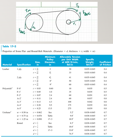
Belt/ Pulley Selection
With reasonable bearing reactions and a belt force found with respect to a motor radius of 1.5” and a shaft pulley radius of 3”, the belt was designed with both radii constant. Ideally, a V-belt would be used to transmit power from the motor to the shaft. A V-belt would provide slip for impact cutting forces from the flywheel. However, the minimum sheave radius for a V-belt running at 16 hp was far greater than the design’s maximum sheave radius. Thus, a round or flat belt that matched the minimum sheave requirements of r1 (3 in) and r2 (1.5 in) was used. Further details of the belt and pulley are described in the analysis file above.
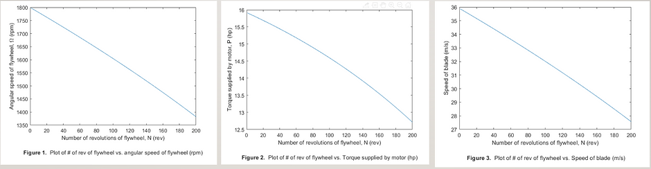
Graphical Analysis
A work-and-energy method was used to analyze how rpm of the flywheel changes over the number of revolutions required to chip a typical log or branch of Oak. As a result of the analysis, it was found that the rpm of the flywheel would drop from 1800 to roughly 1270 after 200 revolutions, which would be equivalent to chipping 4.16 ft long oak branches with 4 in diameter. For speed of the blades on the flywheel, it would drop from 36 m/s to 28 m/s after 200 revolutions. Based on research, the ideal range of blade speeds for chipping was between 20 and 40 m/s, so even after 200 revolutions, the blade speed was still within the ideal range. For power supplied by the motor, it would drop from 16 hp to 12.7 hp after 200 revolutions.
RESULTS
Our design team utilized a combination of researched testing data and our own knowledge of mechanical system design in order to develop a lost-cost, high-functioning woodchipper that would meet the needs of California residents. Due to limited resources, this was the end of the project. Our next step could have been producing a prototype woodchipper to see how the housing and frame of the chipper would need to be designed to fit our mechanical components. We would then develop some of our own testing to determine if there are any modifications that would need to be made to our initial design.
