CARABINER
October 2020- November 2020
Team members:
Sangmin Sung, Rebecca Hansen, Grant McDonald, Vanessa Wentworth
As a prototype for an aluminum 3D printed carabiner, the PLA design was to be tested at a scaled fraction of the requirements of an actual climbing carabiner. The carabiner was designed to sustain 300 lbs open gate load and 900 lbs closed gate load.

DESIGN PROCESS
Exploring PLA material properties
The first step to optimize carabiner design was to discover the yield strength and modulus of elasticity of 3D printed PLA because they vary with infill density, print raster angle, and print orientation. Table below describes the nominal calculated values of material properties for Hatchbox PLA at 80% and 100% infill from Cal Poly in-house testing. Our team discovered that a raster angle near 40-45 degrees would be ideal, and that high infill density would be ideal since tensile strength would increase. Our team was given no control over infill pattern, so rectilinear was used for the infill pattern. Since shell thickness of the carabiner was critical to its strength, our team decided on 4 layers of shell thickness to maximize the strength.

Fundamental Mechanics of Carabiner
Modern climbing carabiners are typically rated to at least 20kN along the major axis with the gate closed, and 7kN along the minor axis with the gate open. A diagram presenting standards is provided in the image below for illustration. Since this project was utilizing PLA as our base material, these strength requirements were scaled down.
Knowing that our part was going to be tested in the open configuration, we focused our analysis on this configuration where the ultimate load capacity is 300 N. For testing, a rope would be attached to each end of the carabiner, with one end fixed and the other end slowly pulled away, while deflection and tensile force would be measured at increments throughout the loading.

Topology Optimization
Given a 3D-Printing design challenge with a weight minimization goal, our group wanted to make use of a computer-optimized geometry that would otherwise be difficult or impossible to traditionally manufacture, potentially giving the proposed design an edge on an established market. We attempted to utilize topology optimization to generate a desired geometry of our carabiner.
Initial Step to Topology Optimization
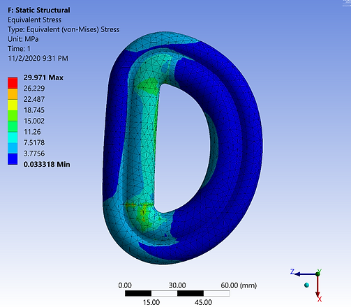
The part surfaces were thickened to “scale up” the part so that the reductive software would have some design space to work with. The modified part was imported into ANSYS Mechanical where it was meshed and solved for as a static structural problem with a ramped load on the upper rope contact area, and an elastic support on the bottom rope contact area, yielding the stress results as shown (with exaggerated deformation).
Since the geometry had been thickened, it was no surprise that the original max stresses were significantly below our design point of 56 MPa. As expected from curved beam theory, the highest stresses were at the inside fiber at both tight corners, and the efficiency of the cross-section could be seen by the outside fiber and even the mid-fiber holding some of the load. Due to the D-shape configuration, most of the load was carried through the straight member, rather than through where the gate would be.
Results of Topology Optimization
The results from the initial stress analysis were then fed into a topology optimization study, again in ANSYS Mechanical, where the software was meant to reductively reduce the part mass by eliminating mesh elements that support little to no load. My guessed input requested that the software would remove the least useful 50% of the material.
The simulation ran for only seventeen iterations before reaching the 50% mass goal, which might have been a red flag that the first 50% was “too easy” and that more work could be done meticulously carving into the remaining material for more light-weighting. Potential evidence of this could be found in how the algorithm did not see fit to attempt optimization of the heavily inflated cross section, and only cut material on the straights where expected stresses are lower without the curved beam amplification phenomenon. What was unexpected was that the two seeming “bite marks” taken out of the inner right side, which were likely just remnants of the solve constraint to not modify the functionally critical inner D-shape surface.

Post Processing
To prepare these rough results for validating analysis and printing, the mesh body was imported into ANSYS SpaceClaim modeling software for smoothing.
Unfortunately, the topology optimization process eliminated the boundary condition surfaces at the mesh body operation and could not be recovered or reconstructed for the smoothed body (even though the said surfaces were selected to be unmodified through the study), given the skillset and experience level available. This unfortunately signaled the end of the topology optimization study before the part could be shown to withstand the necessary loads, reiterated, and be compared with the other potential designs. Our team moved onto a simpler design of carabiner that would meet the design requirements.

Finalizing Geometry of Carabiner
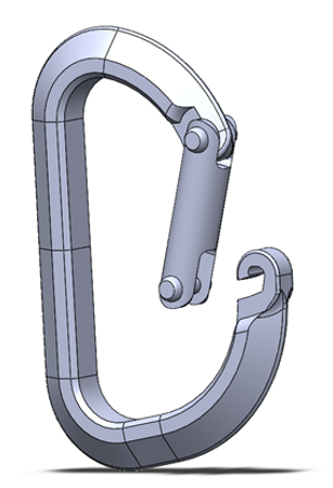
The trapezoidal cross-section (adjusted for 3D printing compatibility) was modeled in a D-shape configuration along with the gate design. The resulting model has a major length of 80 mm and similar angular geometry to the Black Diamond carabiner given. Our design was expected to meet the load requirements without a great amount of material, so the size would generally match that of a standard carabiner, rather than being inflated where the geometry would need to be scaled when applying the design to a stronger material.
The final model is shown below
Free Body Diagrams of Open and Closed Configurations.
Analytical hand calculations were performed using curved beam theory for the open configuration and Castigliano’s method for closed. MATLAB was then used to iterate through different cross-section geometries to minimize the section area and consequentially minimize weight. All calculations and MATLAB code can be found in the report file

Finite Element Analysis
The desired results were for the stresses to be equal to the material strength (56 MPa for yield), such that our part would fail exactly at the design load. However, the modeled geometry was a modified version of the geometry considered in the hand calculations with added material to make it compatible with 3D printing, so it is expected for the stresses to be slightly lower in FEA. With this consideration, the only 8.1% difference from the trapezoidal hand calculations provided validation for both models. The closed gate configuration was much more difficult to analyze, and the FEA was a crude approximation of an actual gate design, so these results were not validated, but they did serve as an assurance that the design likely had the capacity to meet the closed gate load requirement.
Deflections were not calculated by hand, and we were not given any deflection requirements, so there was little numerical evaluation to be done here. The reason to consider deflection was to make sure the gate would remain within tolerance to have a functional fit, and for the rope to not slip off in the open configuration. There was no worry here for the gate fit while operating in the elastic region, since the closed deflection was very small. Additionally, the gate design had a feature where if the carabiner stretched, the gate hook would sit into a divot and become more secure from opening when loaded. Unfortunately, the open deflection FEA did not predict the dangerous rope slippage that occurred during testing, since the flatter end of the D-shape was fixed in FEA, the bottom section appears to not deflect at all.

Manufacturing method
Our team decided to implement FDM (Fused Deposition Modeling) to manufacture our prototype carabiner. The following design concepts for FDM were used as a guide during our design process:
The carabiner was designed for orientation such that the structure is supported without scaffolding during the entire print process by limiting the overhang angle below 60°, as recommended by Mustang 60. This reduces post-processing, which is not feasible for our remote team.
Since the greatest stresses on a carabiner take place at the surface, shell thickness is critical.
No threads were printed, as they do not turn out well for 3D printing processes.
To simplify calculations, we assumed that PLA is isotropic, though the material likely has much greater strength in the continuous direction than in the layer bonding directions, and the infill will have different properties than the outer walls.
RESULTS
Two tensile tests were performed: the main carabiner failure test, and a reference test of the two supporting ropes linked together.
The most significant detail from this test was that the rope slid out along the wider curve at high loads. However, the part did fail in the material before the rope slid off completely. From this close-up view just before failure, potential print issues (that may or may not imply structural issues) could be seen at the edges of the part:
As in the FEA analysis, significant curvature occurred in the spine since the lever arms to the rope applied a bending moment on each end (as depicted in beam tables with end moment loading).
The rope’s travel outwards contributed to the machine extension measurement and caused a larger moment than expected at the critical point, where a crack appears to have developed.

Conclusion
The design exceeded the tested open gate load requirements and was one of the class’s higher specific strength solutions, but much else was left to be validated. Due to limited resources, only one test was conducted, where more tests were needed to prove statistical validity of the results and to provide data on the transverse loading (which wasn’t considered at this phase of the design) and closed gate configurations. More descriptions of the results of our design are shown in the table below.
