FLUID POWER VEHICLE CHALLENGE
April 2021- Present
Team members: Sangmin Sung, Travis Welch, Eddy Rodriguez, Jeremy Baechler, Kevin Pauls
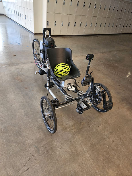
Fluid Power Vehicle Challenge focused on iterating on and designing a fluid powered vehicle that would perform well in the annual Fluid Power Vehicle Challenge, hosted by two fluid power companies, Danfoss Power Solutions and Norgren. The competition was based on three physical challenges: sprint challenge, endurance challenge, and efficiency challenge. To build a competition’s winning design, my team focused on the following implementations: a composite frame design in the hopes of reducing overall vehicle weight, hydraulic hardlines to reduce the overall loss of hydraulic power in the system, a custom user interface that would actuate valves and acquire data, and a pneumatic adjustable seat with double acting pneumatic actuator.
OBJECTIVES
The competition, hosted by the National Fluid Power Association (NFPA), requires teams to design, build, and test a hydraulically powered vehicle that maximizes efficiency, endurance, and sprinting capabilities. This requires teams to combine two types of input and output power cycles that include the use of an accumulator for energy storage, an electronic control system, a regenerative system, pneumatics integration. The design must consider safety, efficiency, and ergonomics, and all design choices must be supported with rigorous engineering analysis that demonstrates an understanding of hydraulics and industry knowledge.
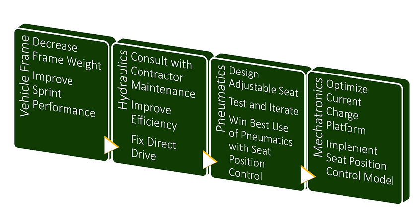
Our team design features a lightweight horizontal carbon fiber frame and an innovative use of pneumatics that will be capable of moving the seat holding the driver forwards and backwards and locking in place. The goal with this design is to place 1st in the competition for efficiency challenge, sprint challenge and endurance challenge of the competition. With the vehicles frame made of high strength carbon fiber, an updated more efficient hydraulic system, and innovative pneumatic and mechatronic implementations, the competition’s winning design can be built. The scope of our project is described in terms of four different subsystems as shown below.
VEHICLE FRAME
The frame design consists of the components described in the table below. The first three components in the table are composite tubing and are planned to be purchased from a composite supplier and manufacturing company called RockWest Composites. The long intermediate modulus square composite tubes have 9 checkered weave pattern layers of carbon fibers, wall thickness of 0.065”, and tube length of 66”. The three circular composite tubes have 20 2x2 Twill pattern layers of carbon fibers, inner diameter of 1”, and outer diameter of 1.252”. The last three components in the table are made of steel and are planned to be manufactured. The steel inserts are planned to be adhesively bonded to the composite tubes with the structural adhesive called Loctite EA 9392. This adhesive is an aerospace grade structural adhesive which cures at room temperature. The assembly of the frame parts is shown below.

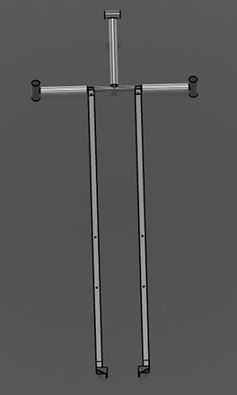
The process to figure out the crank angle and seat position is important as it will affect the performance of the rider when in direct drive. To investigate the optimal crank angle and seat position, our team created a wooden part shown in the image below. The ideal seat distance that our rider feels the most comfortable is 38”, which is within the possible seat distances ranging from 31.73” to 39.32”. The ideal crank angle is 27° relative to the seat.

Ackermann Steering Concept
The steering mechanism design resembles that of an Ackermann steering linkage. This ensures that the turning radius when cornering the vehicle is correctly adjusted to inner and outer front wheels. This also allows for even wear of the front tires, and a display of this concept is shown in the image below.


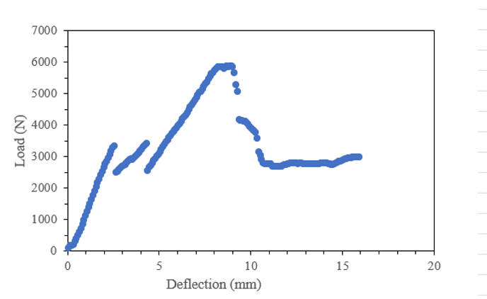
The graph shows results of the 3-point-bend test for carbon fiber square tubes
3-point-bend test Video
Frame Bonding
The frame assembly was consisted of steel tubes and carbon fiber tubes. The carbon fiber tubes were adhesively bonded to the steel tubes with epoxy. It was important to ensure that the bonds would be created properly within a 1 mm clearance gap between the tubes. The tubes were laid on 3D-printed jigs to be cured for 24 hours.


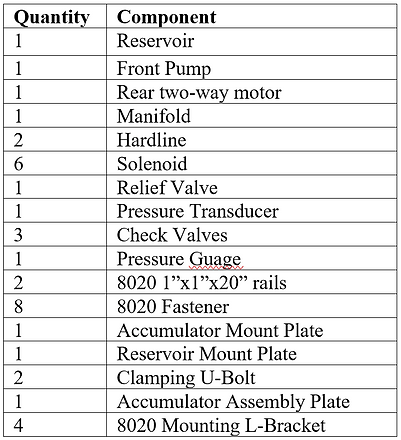
HYDRAULICS
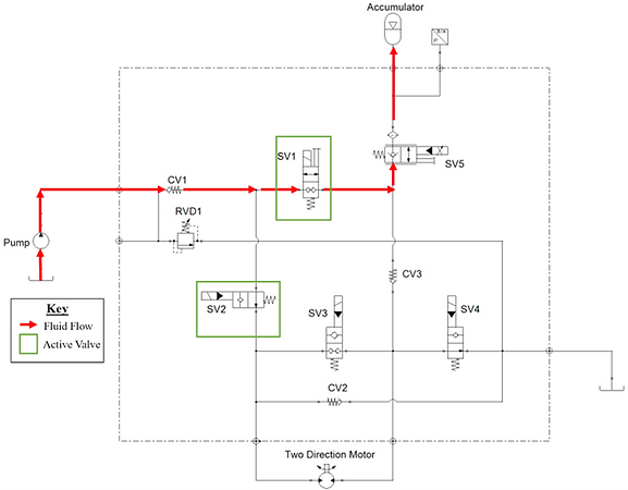
There are currently 5 drive modes available with the current hydraulic manifold circuit: Direct drive Mode, Boost Mode, Regenerative Braking Mode, Coast Mode, and Pedal to Charge Mode. The red line arrows in each image below show the direction of flow for the hydraulic fluid through the schematic. The hydraulic component specifications can be found in the report file shown at the end of this page.
Direct Drive Mode
The hydraulic circuit below is the direct drive mode, which is the solenoid default position for the bike. In other words, none of the solenoids need to be energized to be able to use this mode. This mode will be utilized mainly during the endurance challenge of the competition.
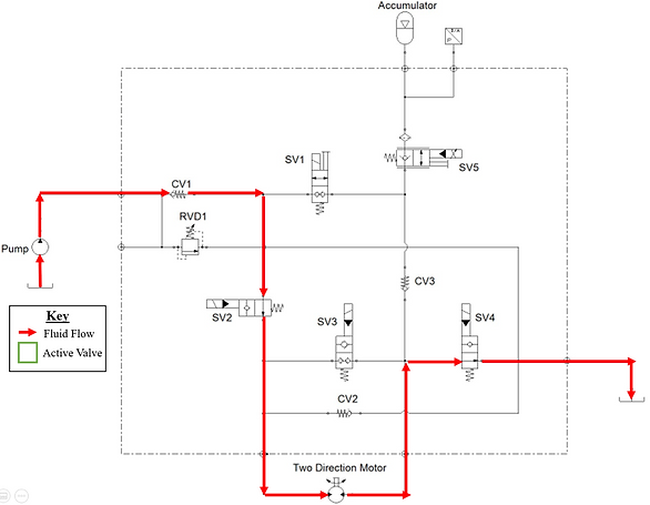
Boost Mode
The hydraulic circuit below is the boost mode. This is the accumulator discharge mode in which all the built-up pressure in the accumulator is released to the rear motor of the bike, propelling the vehicle forward. This mode is used in the efficiency test and sprint race of the competition. Two solenoids need to be energized to use this configuration, one of which is named SV5, regulating the flow through it to control the speed and pressure of the fluid through the rest of the circuit.
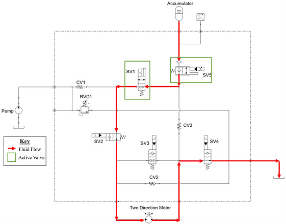
Regenerative Braking Mode
The hydraulic circuit below is braking regeneration mode, in turn switches the accumulator into charge mode building up pressure. This mode uses the translational velocity of the vehicle and the friction of the ground to turn the rear motor, effectively turning the rear motor into a pump, pumping fluid back up into the accumulator. This mode effectively acts as a brake as the pressure gets higher in the accumulator, thereby slowing the bike down. This mode is harnessed in the endurance test of the competition and must show that the vehicle can move forward from the regeneration mode of the circuit.
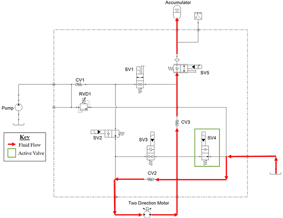
Coast Mode
The hydraulic circuit below is the coast mode, which is used to allow the vehicle not to use all the stored energy during the competition. There is only SV3 that is energized to allow the bike to freely move forward when utilizing this circuit.

Pedal to Charge Mode
The hydraulic circuit below is the pedal to charge mode, which is crucial for the sprint and efficiency tests of the competition. This mode is utilized when the bike is stationary before races or during races because it helps charge the accumulator intermediately. The pedal to charge mode allows the driver to pedal and charge the accumulator directly through the front pump, and the SV1 and SV2 solenoids need to be energized to use this mode.
Hardline Justification
The implementation of flexible high pressure hydraulic hardlines is crucial for our hydraulic system because it helps improve the overall efficiency of the fluid power. Hardlines are hard to manufacture and need to be installed correctly so our team consulted with contractors' maintenance in San Luis Obispo throughout the project as they have a vast variety of hydraulic parts and fittings.
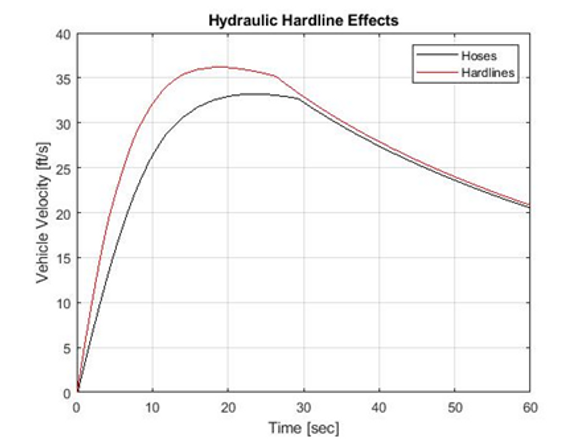
To justify the design decision of hydraulic hardline, the Simscape Simulink for the boost mode is used to verify the efficiency with and without hydraulic hardlines. This model has the power to account for fluid losses through solenoids, check valves and hydraulic lines as well as account for losses due to the environment such as drag force and rolling resistance of the tires.

Below is the simulated graph of the block diagram for the hydraulic circuit in boost mode with and without hydraulic hardlines. Adding hardlines to the boost mode in specific increases the efficiency of the bike by roughly 11% using this model.
PNEUMATICS
The pneumatic schematic below summarizes the pneumatic subsystem assembly. It displays the relationship between components and their physical location. This schematic does not include the electrical wiring required to operate the entire system.

The double acting actuator is attached to the bottom of the back seat plate for adjusting the seat position by sliding the seat back and forth upon button press, and hoses (not shown in the image) are routed from air tank to the actuator. One small spring-loaded pneumatic actuator is attached to the bottom of the front seat plate for the seat locking mechanism. When the small actuator is actuated, the disc rotates to allow the locking rods to be yanked up to lock the seat. There are two pressure regulators used for the pneumatic system. One of them is used for the locking mechanism; the other one is used for the double acting actuator for adjusting the seat. More descriptions of the pneumatic components can be found in the report file at the end of this page.

Solenoid valves
The 5/3 solenoid valve have 5 ports and three states and control the double acting pneumatic actuator. The one of the three states allow air flow to the back of the actuator that extends the cylinder rod; the other state allow air to flow towards the front of the piston that retracts the cylinder rod; the last state pressurizes both side of the actuator to keep a center position. The 5/3 solenoid valve has an operating range between 21-116 psi that would work for our operating system pressure of 100psi. The image below is the specification of the 5/3 solenoid valve.

For the locking mechanism, the smaller actuators are connected to a 2/2 solenoid valve. The 2/2 solenoid controls the air flow going into the one-way spring-loaded actuator. The 2/2 solenoid valve will normally be opened to allow small pneumatic actuator rod to remain fully extended. In this configuration the seat will normally be locked unless the 2/2 solenoid valve is excited to cause the smaller actuator to fully retract. The image below is the specification of the 2/2 solenoid valve.

Demo Video
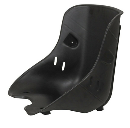
The selected seat attached to the seat plates is a go cart plastic bucket seat, which is relatively low weight but still very durable and stiff.
MECHATRONICS
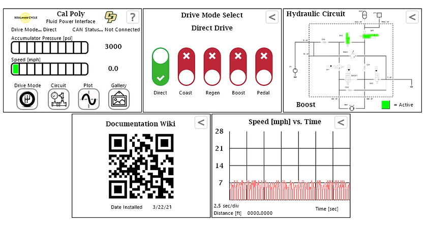
Touchscreen User Interface
The touchscreen User Interface allows the driver to change drive modes of the hydraulic circuit, monitor what solenoid vales are currently activated, and measure real time accumulator pressure and current speed of the vehicle
Communication of signals
The mechatronics system is consisted of the following components:
Custom user interface
Hydraforce PLC valve driver
CAN bus for networking electronics
Quick Press manual buttons
The custom interface holds the controller that will be the master to all other components of the mechatronics system. It signals to the hydraforce valve driver to open the correct solenoids when directed by the user buttons. It also picks up the speed and pressure sensor readings that will be displayed to the user when desired.
